1.1 What is computational design?
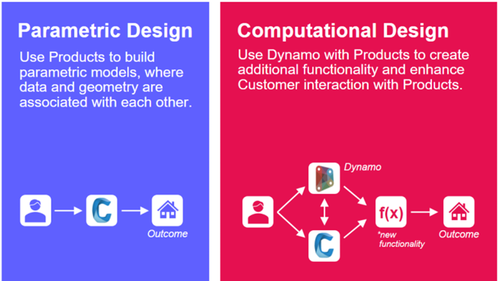
Parametric design allows users to draft objects in a design software using the software’s parameters and functions. Computational design allows for the user to create custom functionality inside or alongside the design software.
1.2 Accessing Dynamo for Civil 3D
Dynamo is automatically installed for C3D 2021+. For C3D 2020 and earlier, Dynamo must be separately installed as an add-in program. Dynamo can be found under Civil 3D’s “Manage” tab in the “Visual Programming” panel shown below.
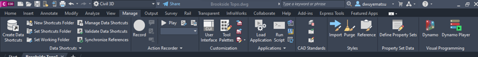
The first option “Dynamo” opens the Dynamo Node Space. The Dynamo Node Space (DNS) allows you to create, edit, and execute Dynamo programs directly. The “Dynamo Player” is a convenient user interface feature used to execute existing Dynamo programs more efficiently.
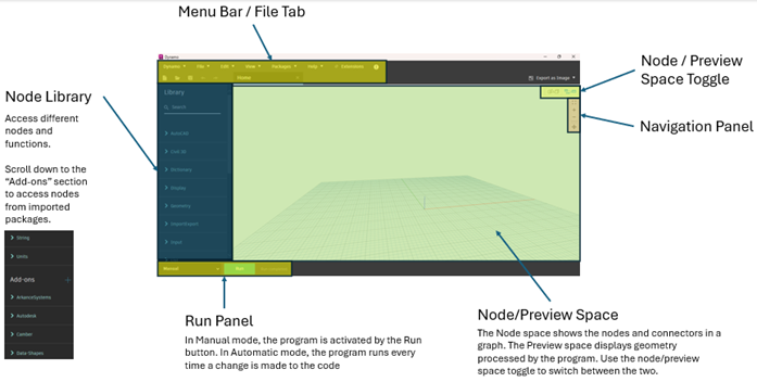
1.3 Dynamo Layout
1.4 Create Your First Program: Get Layer Names
Let’s create a Dynamo program!
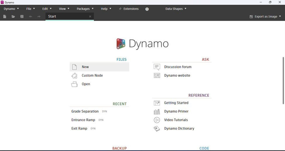
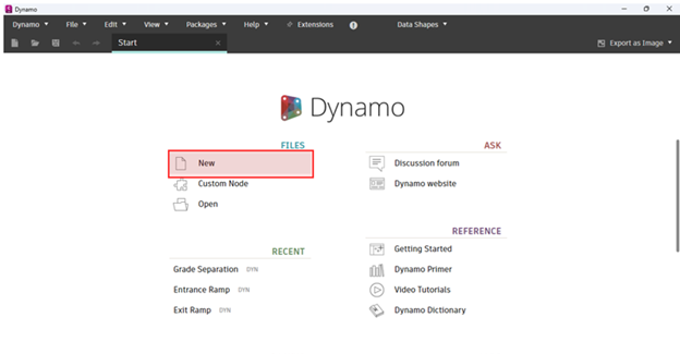
1) First, create a new program:
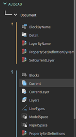
2) In the Node Library, add the Document.Current node to the Node Space by navigating to AutoCAD > Document > Current
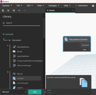
The Document.Current node is added to the Node Space. The Document.Current node is used to refer to the current document open in your C3D model space. It is the first node of almost every Dynamo program.
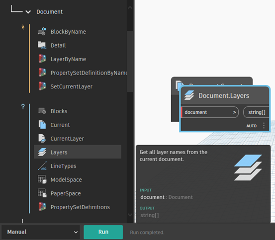
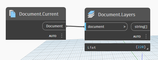
3) Select the Document.Layers node under AutoCAD > Document > Layers
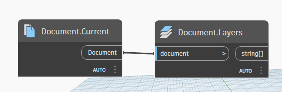
4) Reorganize the two nodes and connect the Document.Current node to the Document.Layers node.
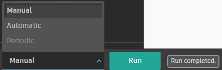
5) Run the program. Make sure the Run mode is set to “Manual” to the right of the Run button. Hover over the Document.Layers node. A tab “List … {220}” should appear below.
6) Hover over the right side of the “List” tab at the bottom of the Document.Layers node. Click the pin button on the right side of the Document.Layers output.
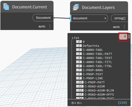
The Dynamo program produces a list of all the layers in the document.
1.5 Node Inputs
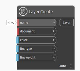
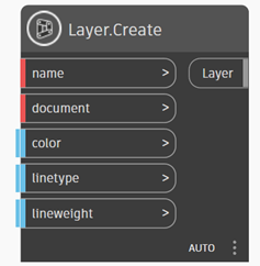
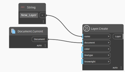
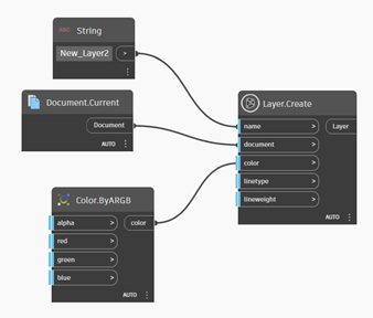
Complex nodes require multiple inputs. In the example below, the Layer.Create node requires 5 inputs to output a layer. A red bar in front of an input indicates that a node does not have sufficient information. A blue bar means the node is connected. Inputs with default values are noted with a double blue bar. Inputs with default values don’t require an input connection. Default values can be overwritten with a regular input connection.
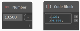
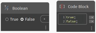
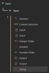
The three most common input types are strings, numbers, and booleans.
String: a sequence of characters usually used for naming purposes
Number: a numeric value - “double” refers to numbers with decimals; “int” refers to integers
Boolean: a binary True or False variable used for conditional statements
1.6 Create Program: Create New Layer
Following this exercise will give a better understanding of node inputs.
1) Set the run mode to manual.
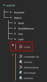
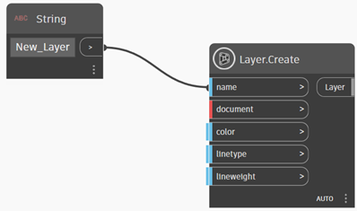
2) Add the Create.Layer node to your Node Space.
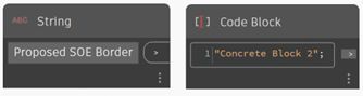
3) Add a string to the “name” input.
4) Set the current document as input using the Document.Current node.
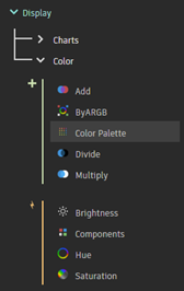
5) Add a color using the Color Palette node.
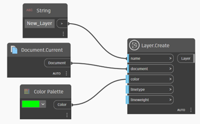
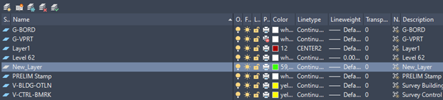
6) Run the program. Go to the Civil 3D model space and open the Layer Properties Manager (shortcut “LA”). Notice the new layer created from Dynamo.
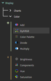
7) Instead of using the Color Palette node, let’s use the Color.byARGB node. Place the Color.byARGB node in the node space and replace the Color Palette’s connection to the Layer.Create node.
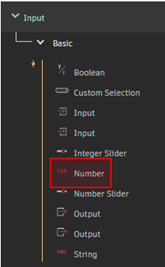
8) Add Number node inputs and adjust the values to customize your new layer color. Change the layer name in the String input.
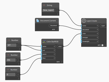
9) Run the program again to create your second layer. Go to the Civil 3D model space and open the Layer Properties Manager (shortcut “LA”). Notice the new layer created from Dynamo.
1.7 Useful Keyboard Shortcuts
Ctrl + N New Graph
Ctrl + O Open Graph
Ctrl + S Save
Ctrl + A Select all nodes
Ctrl + G Create group of selected nodes
Alt + Left Remove node from group
Ctrl + W Create a note block
Ctrl + C Copy nodes
Ctrl + X Cut nodes
Ctrl + V Paste nodes
Ctrl + Y Redo
Ctrl + Z Undo
Ctrl +/- Zoom in / out
Ctrl + 0 Zoom extents
Escape (Hold) Switch to Background view
Tab Select connected nodes
F1 Node help documentation
F5 Run Graph (from Manual mode)
See https://primer2.dynamobim.org/a_appendix/a-6_dynamo-keyboard-shortcuts for more.