Lesson 2: Geometry Nodes
This lesson will cover the basics of Dynamo Geometry including points, vectors, planes, lines, curves, and solids.
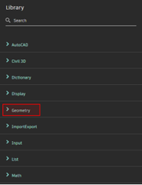
Access geometry nodes in the node library under the Geometry tab.
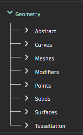
2.1 Points
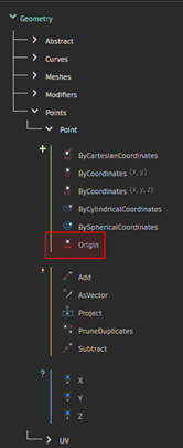
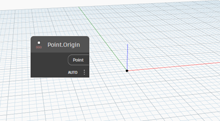
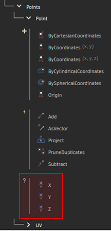
Expand Geometry > Points > Point to view the point nodes. Select the Point.Origin node.
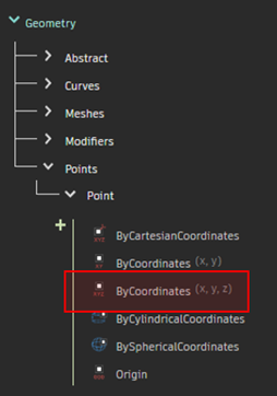
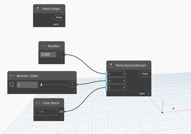
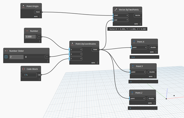
Select the Point.ByCoordinates node.
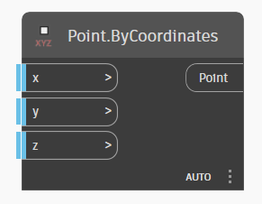
Use any type of number input to adjust the point coordinate values.
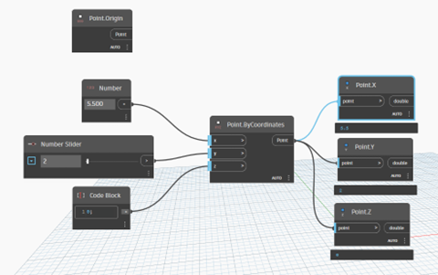
Use the Point.X, Point.Y, and Point.Z nodes to get the XYZ components of the created point.
2.2 Vectors
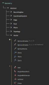
Expand Geometry > Abstract > Vector to view the vector nodes.
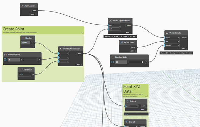
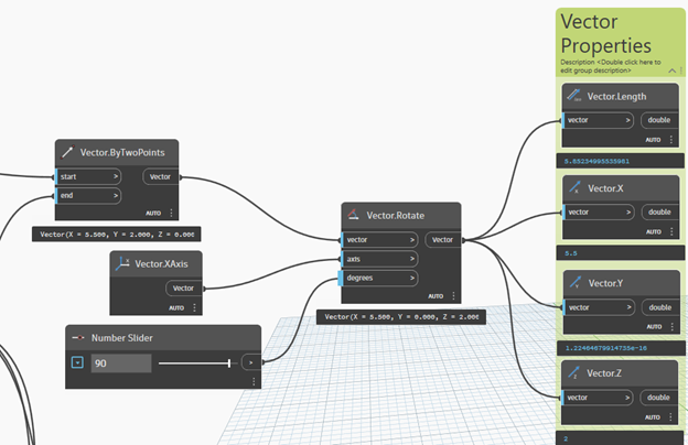
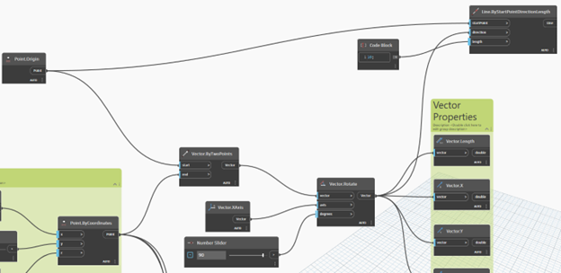
Vectors can be created using the Vector Creation nodes. Create a vector from the origin and the created point using the Vector.ByTwoPoints node.
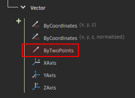
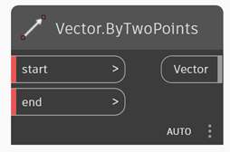
Use Vector.ByTwoPoints to create a vector from the origin to your created point.
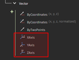
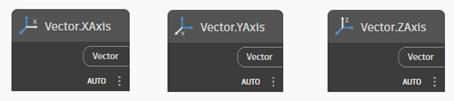
Vectors can be created from the X, Y, and Z axes using the Vector.XAxis, Vector.YAxis, and Vector.ZAxis nodes.
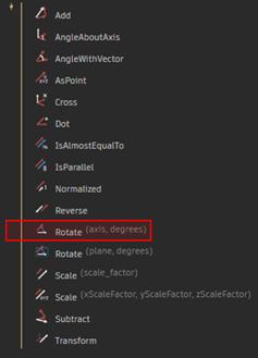
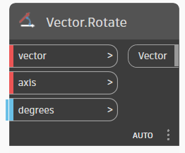
Vectors can be manipulated using the Vector Action nodes. Rotate the created vector about the X axis using the Vector.Rotate node.
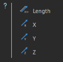
A vector’s properties can be accessed with the Vector Query nodes. Use the Vector Query nodes to display the rotated vector’s properties.
2.3 Lines
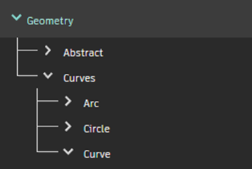
Expand Geometry > Curves > Lines to view the line nodes.
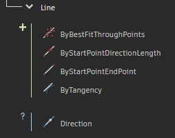
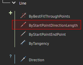
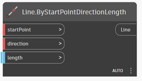
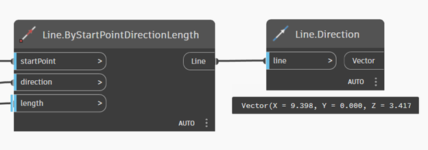
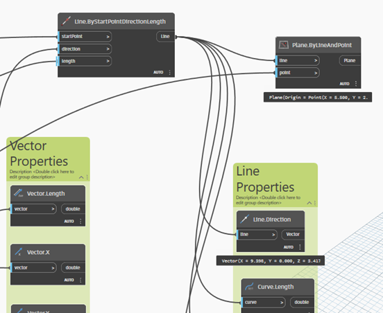
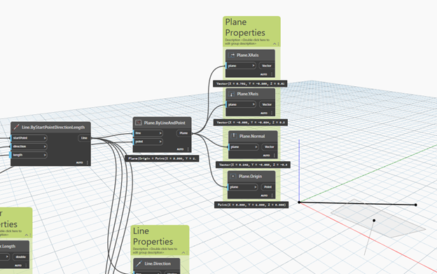
Create a line with your rotated vector and a point using the Line.ByStartPointDirectionLength node.
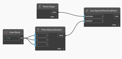
Lines are most commonly created with Line.ByStartPointEndPoint node.
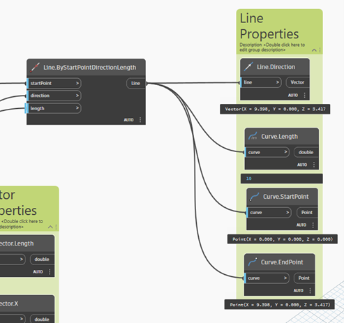
Use the Line.Direction node to get the vector associated with the line.
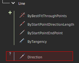
It should be noted that although the Line.Direction node is the only Query node listed for lines, more line properties can be accessed through the Geometry > Curves > Curve Query node list. Lines are a subset of curves, so all of the curve query nodes can be used for lines.
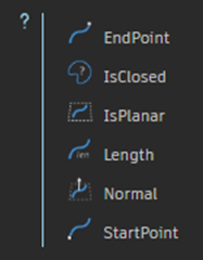
Use the Curve Query nodes to output more properties of the created line.
2.4 Planes
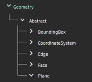
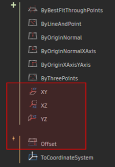
Expand Geometry > Abstract > Plane to view the plane nodes.
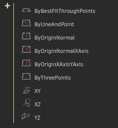
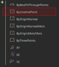
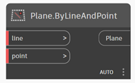
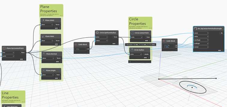
Planes can be created using the Plane Creation nodes. Create a plane with a point and the created line using the Plane.ByLineAndPoint node.
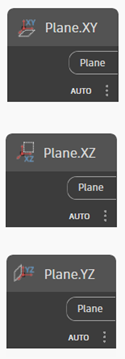
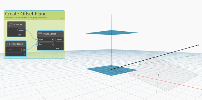
The XY, XZ, and YZ planes can be created with the Plane.XY, Plane.XZ, and Plane.YZ nodes. Create an offset plane above the XY plane using the Plane.XY and Plane.Offset nodes.
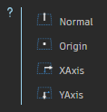
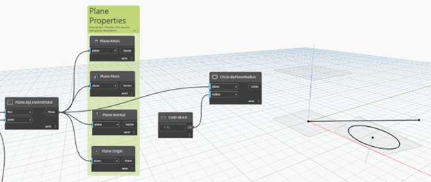
Get the plane’s properties using the Plane Query Nodes.
2.5 Circles
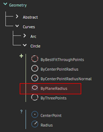
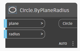
Expand Geometry > Curves > Circle to view the circle nodes. Create a circle with one of the created planes using the Circle.ByPlaneRadius node.
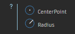
Get the circle’s properties using the Circle Query Nodes.

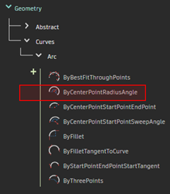
2.6 Arcs
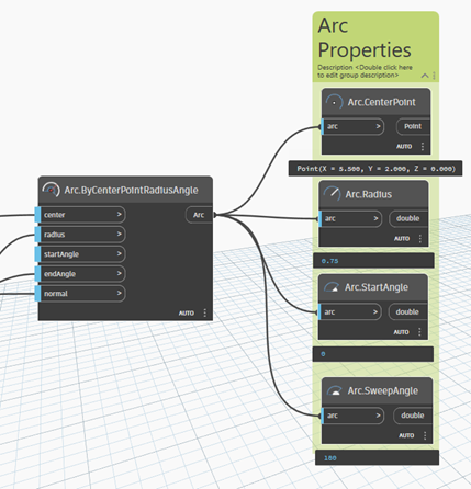
Expand Geometry > Curves > Arc to view the arc nodes. Create an arc with one of the created planes using the Arc.ByCenterPointRadiusAngle node.
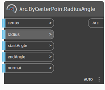
Use the normal vector from one of the created planes to create the new arc. Adjust the radius, startAngle, and endAngle and notice the varying output.
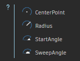
Get the arc’s properties using the Arc Query Nodes.
Save the graph as Geometry_Exercises_2D.dyn. Close the graph.
2.7 Solids
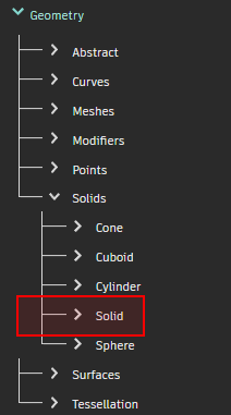
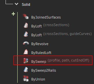
Start a new Dynamo file. Expand Geometry > Solids > Solid to view the solid nodes. The Cone, Cuboid, Cylinder, and Sphere node groups are also useful to create those types of solids.
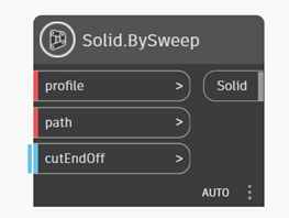
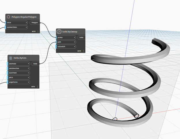
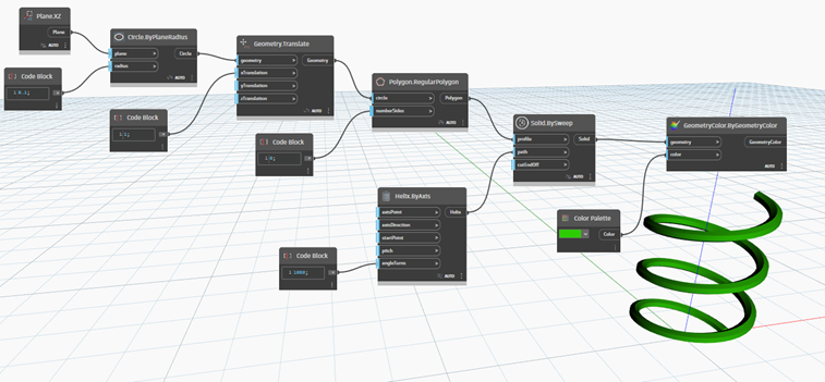
Create a solid from a helix and a polygon using the Solid.BySweep node.
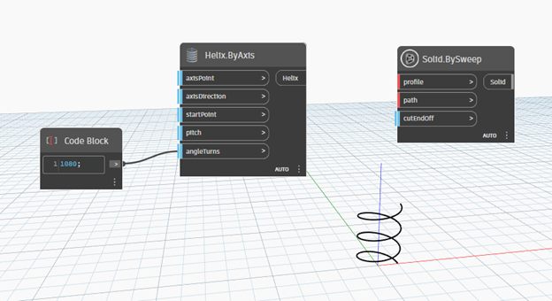
First, create the helical path using the Geometry > Curves > Helix > Helix.ByAxis node.
Next, create the profile to be swept along the helical path using the Geometry > Curves > Polygon > Polygon.RegularPolygon node. Create a circle on the XZ plane and use the Geometry.Translate node to move the center of the circle to the start point of the helical path.
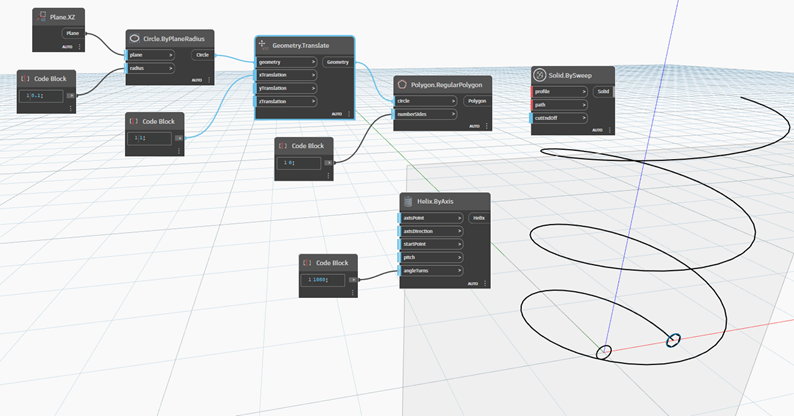
Finally, connect the outputs to the Solid.BySweep node to generate the result.
2.8 Geometry Color
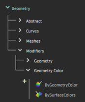
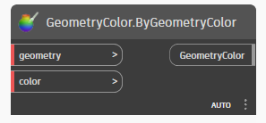
Expand Geometry > Modifiers > Geometry Color to view the Geometry color nodes. Bring the GeometryColor.ByGeometryColor node into the Node Space.
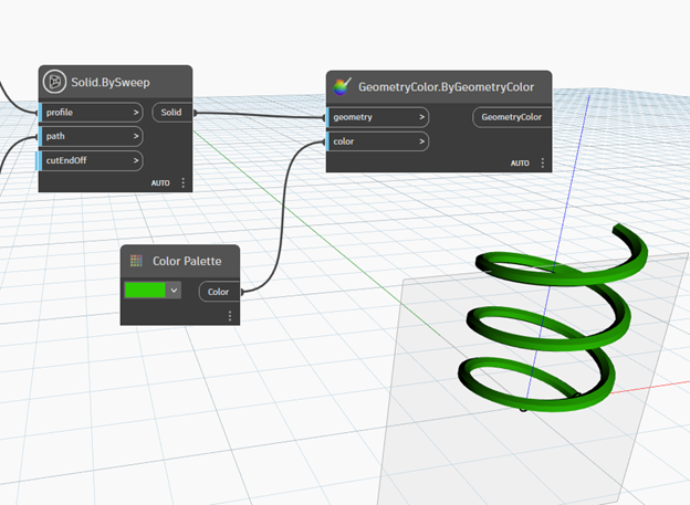
Color the 3D solid with a color. Color creation nodes are found under Display > Color.
2.9 Node Display Settings
To clean up our 3D solid display, remove the geometry previews of nodes. Right click nodes and deselect “Preview Geometry”.
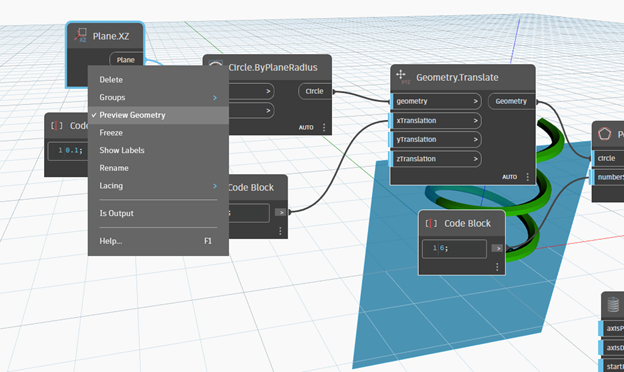
Nodes will show a gray bar underneath to indicate that it’s preview geometry has been disabled.
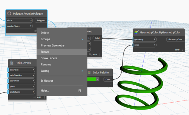
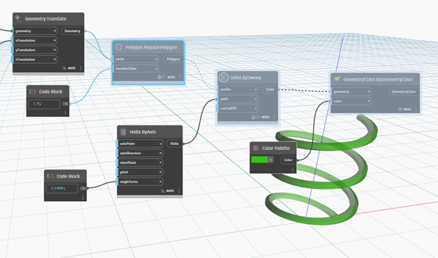
Additionally, nodes can be frozen. Frozen nodes will also disable the output of any nodes dependent on the frozen node’s output.
Save the graph as Colored_Helix.dyn. Close the graph.
2.10 Importing Geometry from the Model Space
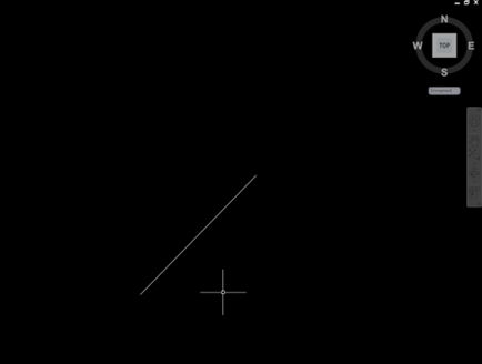
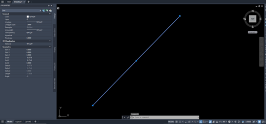
Draw a line in the C3D Model Space (Shortcut “L”).
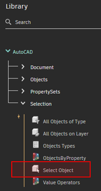
Create a new Dynamo graph. Expand AutoCAD > Selection to access the Selection nodes. Bring the Select Object node into the node space.
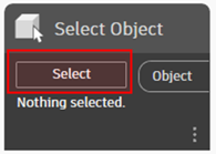
Click the “Select” button in the middle of the Select Object node and select the line in the Civil 3D model space.
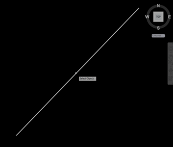
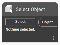
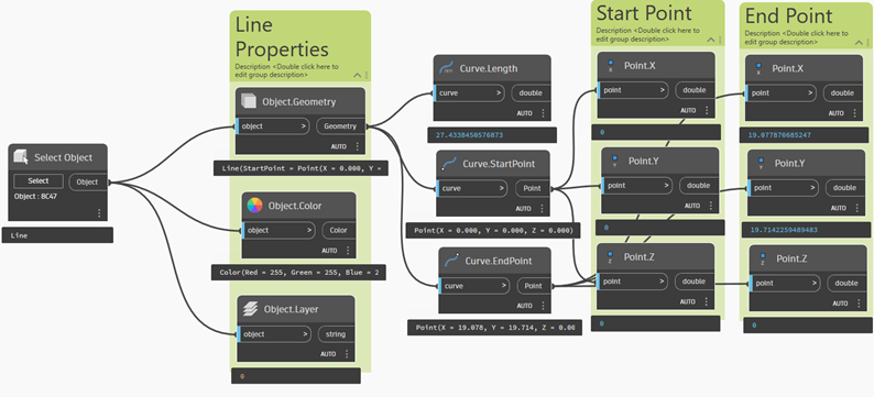
Return to the Dynamo node space. The Select Object node shows the Object ID of the selected object.
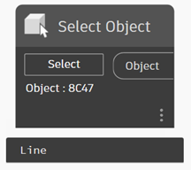
The node output reads the selected object as a Line. This line object is different from Dynamo Geometry lines because line objects contain more information than just geometry. Line objects are assigned to a layer and have a color. Let’s access the line object’s properties using the nodes from the AutoCAD > Objects > Object menu.
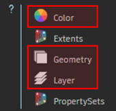
Select the Object.Geometry, Object.Color, and Object.Layer nodes to view the line object’s properties.
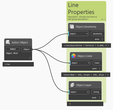
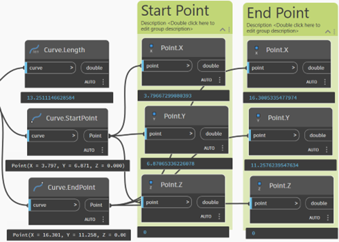
The output from the Object.Geometry node outputs a Dynamo Geometry line. Use the line query nodes and point query nodes to get the line object’s geometric properties.
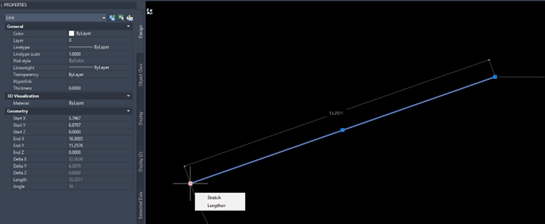
We can verify the query node outputs in Dynamo match the line object’s properties in the Civil 3D model space. Select the line object in the model space and view the properties from the Properties panel (Shortcut “MO”).
Edit the line in the model space and notice the changes in your Dynamo graph output.
2.11 Creating Lines in the Model Space
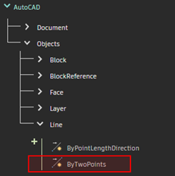
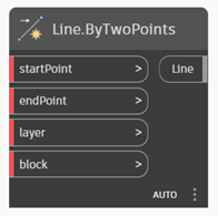
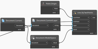
Using the AutoCAD > Objects > Line > Line.ByTwoPoints node, create a line in the model space from the origin to the end point of the drawn line.
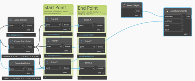
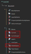
Expand AutoCAD > Document to view the Document nodes. To print the line to the current layer, use the Document.Current and Document.CurrentLayer nodes. To print the line to the model space, use the Document.ModelSpace node. Connect the nodes as shown.
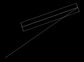
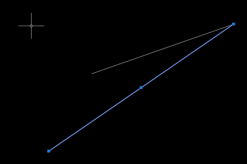
Notice the output in the model space.
2.12 Creating 3D Solids in the Model Space
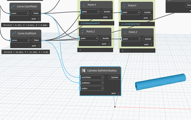
Using the Geometry > Solids > Cylinder > Cylinder.ByPointsRadius node, create a Dynamo solid using the end points of the original drawn line.
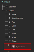
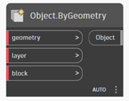
Bring the AutoCAD > Objects > Object > Object.ByGeometry node into the node space. The Object.ByGeometry node is used to bring lines and solids into the model space.
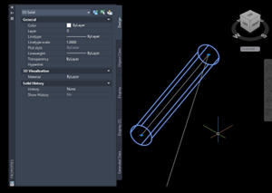
Connect the created cylinder to the geometry input of the Object.ByGeometry node. Use the Document.CurrentLayer and Document.ModelSpace nodes to satisfy the layer and block inputs of the Object.ByGeometry node.
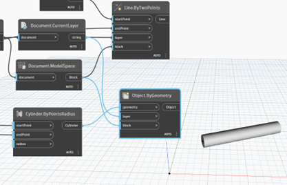
Notice the output in the Model space.